What is a Waveform?
Last Updated on April 24, 2025 by ImageXpert Team
An important part of an inkjet printing system is the waveform that is applied to the printhead, which is the driving force behind the drop ejection. The design of the waveform will directly impact the performance of the printer and print quality, but this waveform design is often not well understood. In this post we will discuss the fundamentals of the waveform – what waveforms are, how they work, and why they are a necessary part of your inkjet development. In the next post, you’ll find practical steps to go through the process of optimizing a waveform for your for your ink. Start with this article, and when you are ready to move on to editing your waveform, learn how to optimize one here.
WHY WAVEFORMS MATTER
The waveform is the electrical signal that is sent to each nozzle on the printhead that causes each individual drop to be fired. This electrical signal is sent to hundreds or thousands of individual nozzles simultaneously, thousands of times per second. The shape of the waveform signal will influence the size and speed of the drops. It also impacts the consistency of the jetting from one drop to the next, across the printhead, and over time. It also dictates the maximum speed that the printer can operate. The waveform holds a lot of power over the performance of the printer, especially for one setting tucked deep into the software that you might not even know exists.
If drop size, jetting consistency, drop placement accuracy, printing speed, or some other requirement of your application demands a high level of performance, optimizing every last detail including the waveform matters. If you are working with a challenging fluid, whether or not it comes out of the printhead or not at all will be dictated by your waveform design. With the right tools, making small waveform changes that bring huge performance improvements is a simple, quick process.
To showcase this, here is what one waveform setting change can do to the quality of your printing process. Both of these images are taken from the same printer, using the same ink, minutes apart. The only difference between them is a changing a single voltage setting in the waveform software.
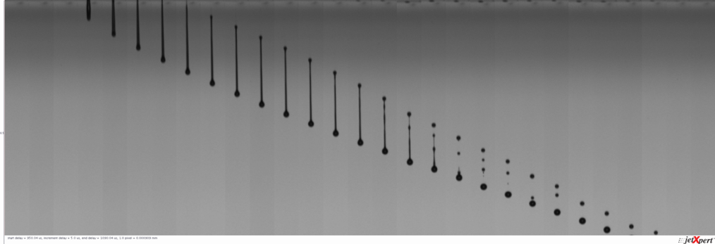
High speed drops, lots of satellites. This is suitable for a large throw distance application that is very forgiving to satellites, such as printing on textiles.
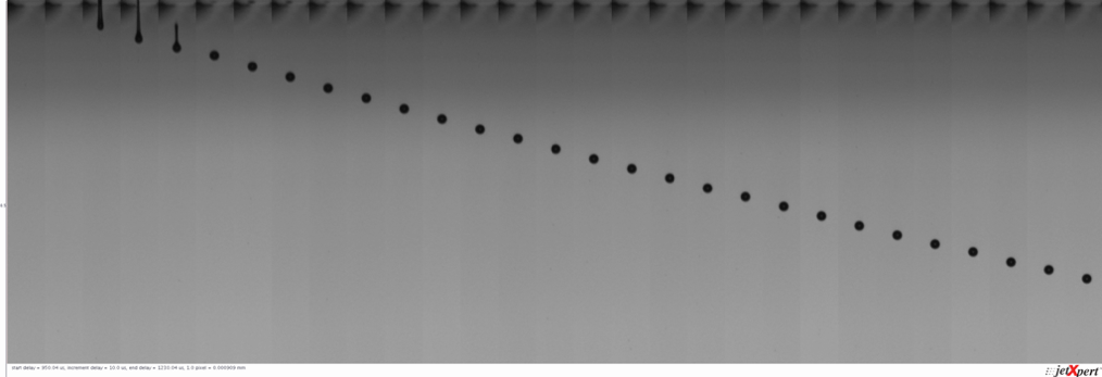
Reduced speed drops, no satellites. This is suitable for a short throw distance application where satellites are problematic, such as printed electronics.
Using the wrong waveform for the wrong application will handicap your printing performance, leaving you to try to find formulation or mechanical solutions to overcome these setbacks. Waveform edits are much simpler, you just need to learn how to do it. Let’s get started!
THE BASIC PRINCIPLES OF AN INKJET WAVEFORM
To help understand how a waveform works, let’s take a look inside a nozzle chamber of a printhead. The image below depicts the jetting process known as fill-and-fire, which is common across many different printhead models. In this case, a stack of PZT (a piezoelectric ceramic material) deforms whenever voltage is applied to it, changing the volume of the ink chamber and causing the ink to move within it. If the ink moves enough, it will leave the nozzle as a drop. The means of applying this voltage to the PZT is the waveform.
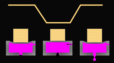
In our example, the PZT is extended only when voltage is applied, so there will be no deformation until the printhead is plugged in. Once powered, the printhead maintains a specific voltage, causing the PZT to extend and remain in its non-jetting position (Left). If the voltage is decreased, the PZT retracts and creates an expansion in the chamber, drawing ink into it (Center). To eject a drop, the voltage is returned to its original value, the chamber shrinks, and the excess ink is forced out (Right). This process repeats thousands of times per second across every nozzle on the printhead.
The waveform is applied to the printhead through the electronics referred to as a printhead “controller” or “drive electronics”. These electronics send the signals and their software will have settings to control the shape of the signal. Here’s an example of a real waveform for a Dimatix printhead and Meteor drive electronics software for designing and applying it.
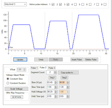
It is important to note that the actual shape of this pulse will vary with printhead design. Some printheads are driven by positive-going pulse, some by negative-going pulses, and some even go in both directions. Whichever way you’re used to looking at it, there are some fundamental settings that determine the shape of the waveform.
- The slope of the rising and falling parts (referred to as “slew rate”)
- The duration of the flat plateua (referred to as “hold time” or “pulse width”)
- The overall amplitude of the pulse (referred to as “amplitude” or “voltage”)
These come together to shape the pulse, which determines what is happening at the nozzle and ultimately how the jetting will perform. Let’s examine the timing in more detail.
PULSE TIMING BASICS
If you’ve stood next to a print head while it is printing, you might have been able to hear it “sing”, depending on what frequency was being used. The reason you can hear it is because the actuators produce sound waves. The most important ones for jetting are the ones that get produced in the ink itself, since they define the pressure variation that gives drop ejection.
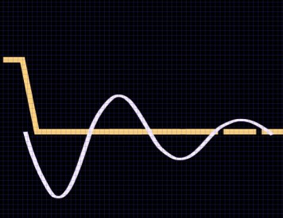
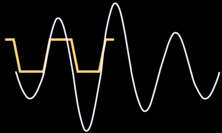
Because of the presence of an ink with certain mechanical properties, and the fact the sound waves can lose energy as they bounce around, the pressure in the chamber can be described as a damped resonator. Any change in pressure, such as the PZT deforming, will result in a characteristic pressure variation. As shown here, when the PZT retracts and the chamber increases in volume, the pressure change causes the ink to begin moving back and forth within the chamber.
This energy alone is usually not enough to cause the ink to eject, it just pulls it back to the opposite end of the chamber and bounces off. By using a voltage pulse to reinforce the pressure at the right time, the drop ejection is made more efficient, as shown here. A drop is ejected when the pressure goes over a critical value due to the preferable timing.
The reason the pulse timing is so critical is that if it is too short, or too long, then the waves, pressure, and movement of the PZT will be out of sync. If the ink is not moving the right direction at the time more pressure is added, instead of smoothly adding to the momentum, the momentum might be countered. It is similar to pushing a child on a swing. If you push them at the right time, the momentum is increased and they swing higher. If you push them at the wrong time, they will come to a violent stop. Similarly, if the pulse timing is wrong, the resulting jetting, repeated over and over, will be inefficient and unstable.
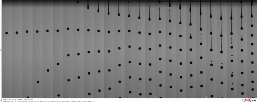
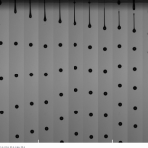
The image below shows the impact of pulse timing on the jetting. We’ve stitched together images of drops using different pulse duration. The time of capture of each slice is the same, so drops that are farther from the top of the image (the nozzle plate) are traveling faster.
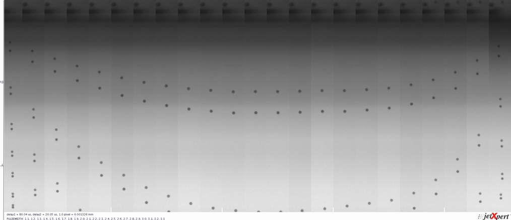
As you can see, there is a clear pattern between how long the pulse is applied and the speed of the drop it produces.
Because the pulse duration is moving the fluid back and forth across the length of the nozzle chamber, and the length of the nozzle chamber is fixed for a given printhead, you might think that each printhead has a specific pulse duration to use. If you need a basic level of jetting performance, this can be true, and you can get a recommended general setting from the printhead OEM. However, the timing is also impacted by the speed of sound for that particular fluid. When you require high levels of jetting performance, the waveform must be tuned for a particular ink and printhead combination.
Join Our Mailing List
WHAT IS RESONANCE?
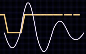
It is common that a waveform that works well at one frequency might not work well at another. This all comes down to the timing of the pulses as the ink moves back and forth within the chamber. As the frequency of the printing is increased, the waves and movement created by a given pulse can start to interact with the previous one. At certain frequencies this is going to be reinforcing and the result is resonance, as in the top example in the image.
The higher the printing frequency, the more likely that the pressure is not yet damped to zero when the next drop and pressure wave comes along, and thus the greater the potential for getting poor firing. If the ink is still moving, the previous pulse could either add to the pressure (higher velocity, more satellites, wetting) or detract from it (lower velocity). If your print speed is flexible, it is sensible to study the droplet formation at a range of frequencies in order to ensure your final print speed does not fall in a frequency range where resonance occurs.
Here’s a real life example of resonance at work. As you can see, the jetting quality is significantly worse at a specific range of frequencies (19-23kHz). The drop velocity is higher, there are more satellites, and the performance is unstable. But at frequencies higher or lower than this range, the performance normalizes. Understanding this phenomenon allows you to set your printer to ensure it doesn’t operate at these speeds, or tune the waveform to minimize the effect.
WHAT IS CROSSTALK?
Crosstalk is a broad industry term for unintended interference between printheads, nozzles, and droplets when printing. Two systems that perform well in isolation might start to show image quality issues when combined together. Crosstalk can be aerodynamic, mechanical, fluidic, or electrical.
We’ve learned that waveforms are thousands of individual signals sent to nozzles, thousands of times per second. Nozzles are packed together closely in the printhead. In a production printer, there are probably dozens or more inkjet printheads nested closely together. Surrounded by motion stages, ink supplies, dryers, UV lamps, and all sorts of other electronics. That is a lot of precision electrical signals happening in a tight space. Understanding your desired waveform shape and expected drop performance will help diagnose any potential electrical interference that happens in a production machine.
Inside the printhead itself, it is possible for one nozzle firing to influence the behavior of the nozzles around it. You might find that the drop volume from a nozzle is slightly higher or lower if the adjacent nozzles happen to be jetting at the same time. A well optimized waveform with that limits excess electrical or mechnical energy can help minimize this.
MULTIPLE PULSES
If the electronics allow it, the waveform doesn’t have to be limited to a single pulse. Multiple pulses can be used at each pixel, which can bring a variety of benefits.
Stringing multiple pulses together allow you to create larger, faster drops than one fill-fire cycle can do alone. Waveforms for multi-pulsing usually rely on the first or second resonance in the pressure wave. This means that the first pulse will add to the pressure of the ink when it is moving towards the nozzle. Some of the ink will eject and the rest bounces off the orifice and returns to the opposite wall. Once the ink is moving towards the nozzle again, a second pulse will add to its momentum. The pulses should be tuned carefully; the reinforcement can be very strong, overdriving the pressure and creating nozzle wetting.
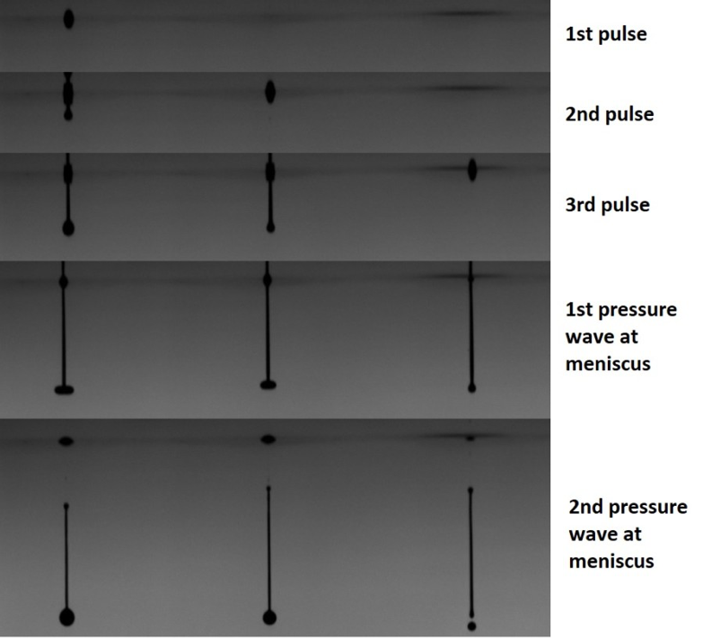
Having the ability to see the drop formation in real time is helpful in understanding these effects. In the photos below, taken with the JetXpert Dropwatcher, you can see drops of different sizes being formed in adjacent nozzles by a resonant multi-pulse waveform. The nozzle to the left had three pulses of a waveform applied to it, the center nozzle only had the last two pulses, and the right nozzle only had the last pulse. The three pulses used to create the drops were evenly-spaced in time, and each image was taken at the time where the pressure wave hit the opening of the nozzle.
Notice the extensions in the nozzle meniscus that happen after pulsing has finished, which are caused by the pressure waves. The first one occurs even before the ligament has separated. The meniscus bumps are larger on the nozzles that have fired twice or more, confirming that extra pressure has been applied thanks to previous pulses. By adjusting the pulse timing and visualizing your progress, you can make improvements to a waveform for a particular ink much more quickly.
The extra pulses aren’t only used for jetting larger drops. It is common to use a pre-pulse on the “off” data to tickle the nozzles, meaning that enough force is provided to keep the ink moving within the nozzle, but not eject a drop. Keeping the ink moving in the nozzle helps slow down drying or particle settling. We discuss this topic in more detail in our article on this Latency effect.
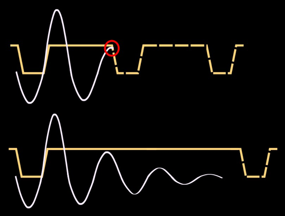
You can also use additional pulses to dampen this accoustic momentum. A well-timed, low voltage pulse that works against the pressure wave in the nozzle will bring the nozzle to a rest state faster. This is particularly useful at high frequencies to cancel the previous drop to avoid resonance.
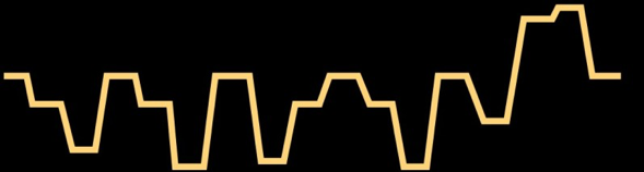
The waveform below has many such features built in and is adapted from a Ricoh patent for a desktop printer.
MAIN TAKEAWAYS
These electrical waveform signals play a big role in the overall performance of the printer by influencing drop size, speed, and stability. For applications that push the limit of inkjet technology, the shape of the waveform needs to be finely tuned for your particular fluid and drop requirements. With the right tools and knowledge, basic modifications to the waveform can be made quickly, which will have a high impact on performance. Ready to get started? Let’s continue on to learn the step-by-step process of how to optimize a waveform for a particular ink.
Referenced Products and Resources
-
How to Optimize a Waveform
Learn More -
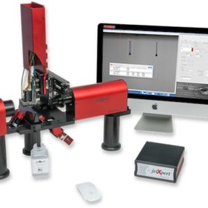
JetXpert Dropwatcher
Learn More -
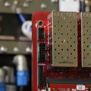
Inkjet Drivers
Learn More