The History of (And Differences Between) Piezo, Thermal, and Continuous Inkjet Printing
Last Updated on June 25, 2024 by ImageXpert Team
In this post, we look at some of the original innovations upon which today’s inkjet printing industry is built and how they have matured into three distinct technologies: piezoelectric, thermal, and continuous inkjet printing. The principal aim is gain some historical perspective and familiarity with the language used, explore some of the differences between the three technologies, and perhaps guide you in your selection of which technology is right for your application. Since we simply love inkjet, it also gives us the chance to pay homage to those the people who started this incredible journey.
EARLY INKJET EMERGES
Prior to the digital age, one of the first “liquid jet” devices was described by Elmqvist in a US patent application dated 1948 (US2566443A), from which the drawing below is copied and modified with annotations.
Rather than being able to print words or images it constituted a form of oscillograph, a type of machine for recording continuously-varying (i.e. analog) measurements. It operated on the principle of a pressurized liquid being squeezed through a fine tube whilst that tube is displaced by a looped coil, driven by an electrical current.
For history buffs, it is interesting to note that the concept not totally different to the famous ink syphon recorder patented by William Thomson, later Lord Kelvin, in an 1858 (UK patent 2147/1867).
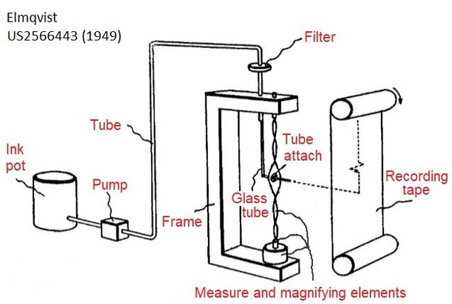
The crux to Elmqvist’s patent was that by avoiding contact with the recording surface, the frequency of operation could be increased relative to previous direct ink writing. It is this specific advantage that makes the Elmqvist device the forefather of the inkjet printers we will discuss next.
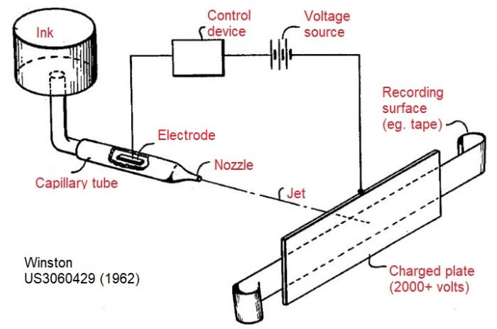
The first “digital” inkjet device to be patented was described by Winston from Teletype. Based on an electrostatic principle it would produce a continuous fine jet, but one which could be switched on and off, with a response time of about 1 millisecond. The annotated patent image below details the key parts of the system, which like the Elmqvist machine, was based on a fine glass capillary tube.
CONTINUOUS INKJET IS BORN
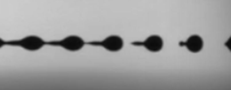
Let’s move forward to the late 1960s, when the first versions of inkjet devices built on the continuous inkjet (CIJ) principle emerged. As suggested in the name, the approach relies on pressurising an ink to form a continuous liquid stream, just like Elmqvist. The key difference this time is that the stream is broken into individual charged droplets by the action of a transducer (or actuator), a device that converts electrical signal to mechanical movement. This droplet breakup is shown in the image below, recorded using a JetXpert system.
It is evident that to achieve a controlled pattern, like text characters, it follows that some of the drops are not wanted. In CIJ those unwanted ones get diverted electrostatically into a collection device (catcher, gutter) whilst the ones that are wanted are permitted to hit the print surface. This selection is achieved by charging the drops as they pass through one set of electrodes and using 1000s of volts from another set of electrodes to push the drop sideways. After the unwanted drops are pushed sideways into the gutter, the ink is recycled back to the start in order to be jetted again. From a design perspective, written characters could be formed, either by diverting a single droplet stream to multiple positions (Lewis & Brown, US3298030) or creating parallel streams (Sweet, US3373437), as depicted in the annotated patent images below.
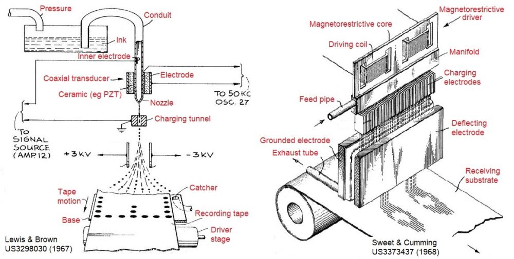
In the design of Lewis & Brown, this was made possible by a piezoelectric element, made from the ceramic lead zirconate titanate (Pb[Zr(x)Ti(1-x)]O3), PZT), which would deform when exposed to electricity. This deformation is what causes the pressure modulation by squeezing the glass filament. In the arrayed design of Sweet & Cumming, the actuator was described as magnetorestrictive, meaning it would change its shape when magnetized.
The CIJ technology proliferated amazingly quickly and by the early 1970s inventions were coming thick and fast from the world’s best-known computer companies like IBM, Casio, Hitachi and Xerox. Today, CIJ systems are some of the most numerous types used in industrial date coding applications. This largely due to the useful polymers that can be carried in the strong solvents (like Methyl Ethyl Ketone) to create fast-drying inks. The faster an ink can dry, the faster you can print – making CIJ popular for high speed applications. This provides the key advantage of industrial suitability, especially when paired with the very high reliability that has been the focus of CIJ printer developers.
Because the solid content can be very low and food-safe, low boiling point solvents (such as alcohols) can be removed effectively in high speed manufacturing lines, food packaging is another key market for CIJ. Direct printing of best-before dates on perishable produce, like eggs, is just one example of the many different places CIJ is used. For a great comparison of different printing technologies that can be used for coding eggs or other produce, check out this article.
Due to its versatility and longer throw distance, CIJ continues to find application into the 21st century. Off the back of ever more sophisticated manufacturing methods, Kodak has developed the CIJ concept into one of the fastest process colour inkjet processes available to meet the web speed demands of newspaper print, for example. We will discuss CIJ and Kodak Stream® technology in specific future posts.
Join Our Mailing List
DROP ON DEMAND INKJET GROWS
Following hot on the heels of the original CIJ inventions, researchers were busy creating designs for ink ejecting devices that produce droplets discreetly (only when they are needed) by using electrical signals. These printheads are generally grouped together as Drop on Demand (DOD) inkjet. Over the years the implementations have been quite wide-ranging, relying upon a variety of physical processes in order to eject a droplet. The most common types in use today rely on sudden localised heating (thermal inkjet), squeezing of the ink with an actuator (piezoelectric inkjet), or releasing pressurized ink with mechanical valves (valvejet).
One key advantage is that the need to pressurize and recirculate ink is reduced, potentially making the ink supply system simpler. There is also less of a need for solvent dosing to control viscosity due to evaporative loss. The fluid compatibility of DOD inkjet is also much wider, including electrically-insulating materials.
EARLY PIEZOELECTRIC HEADS ARRIVE
The first patented PIJ head that looked like something you can still buy today was granted in 1972 to Zoltan, who worked for Clevite Corp, just like Lewis & Brown of CIJ fame. Similar to their design, Zoltan used a single cylindrical PZT actuator, either glued to the end of or wrapped around a fine tube. The lowest voltage of operation could be achieved with the PZT in direct contact with the ink, as shown in the annotated drawing below, but the patent discusses the potential for the ink to be corrosive to the electrode. Thus Zoltan anticipates one of the biggest challenges in printhead design: materials compatibility, a subject that will be re-visited when we talk in more detail about specific contemporary print head designs.
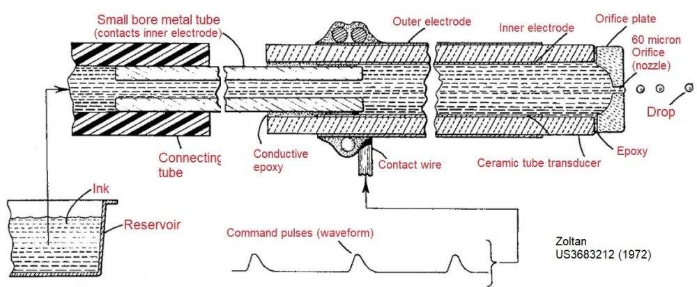
The key difference from CIJ is that the electrical signal to the PZT is applied only when a drop is required. The downside is that the drop is not charged or deflected so several actuators would be needed to form a character printer. Achieving this array with multiple glass filaments was the subject of successive inventions (e.g. US4288799, Canon) but as we will next see, there is a better way.
Granted several years later, the Silonics head described by Kyser and Sears was the first disclosed design to use a flat-shaped (planer) actuator design for a PZT head. This was significant since it allowed for the devices to be stacked together to make a character printer, as shown in the 2nd image, below. Of course there is a certain limitation on the distance between jets, which depends on the layer thickness of all the parts used. Nevertheless, the principle of single-pass printing is made possible, thus anticipating the largest growing application space for industrial inkjet printing today.
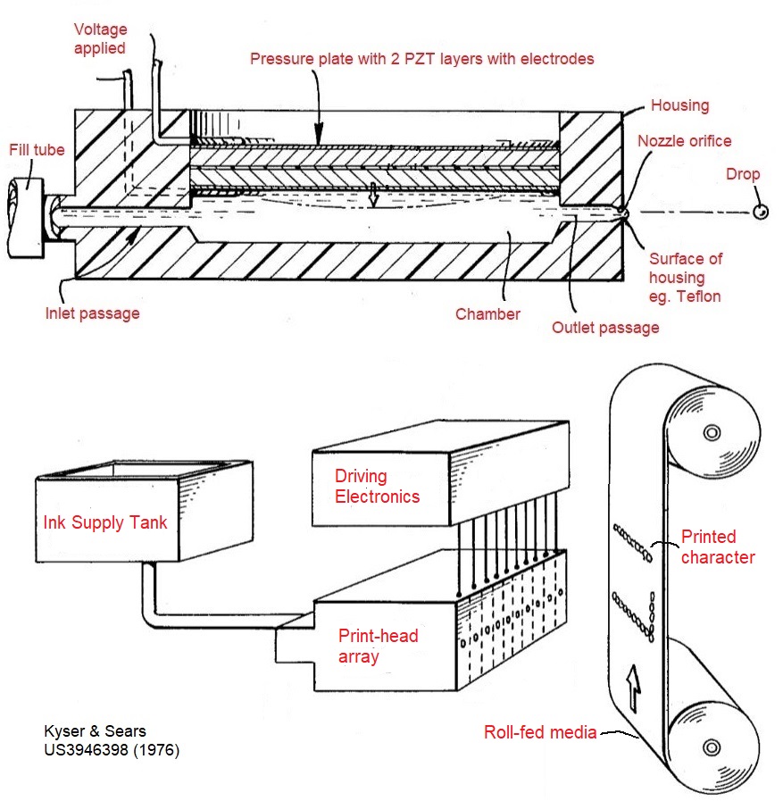
In effect, the Silonics design represents a direct ancestor of the early printheads from Xaar and others, like XJ500, which also use shear mode actuator of the PZT but achieves nozzle spacing at much smaller pitch by more advanced machining of the ceramic and an innovative shared-wall driving scheme.
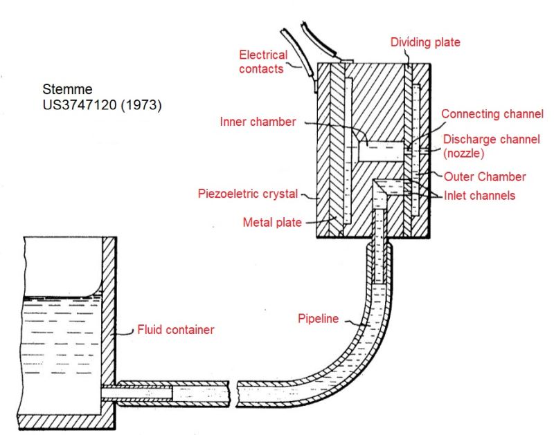
The issue with scaling up the number of nozzles at a better spacing was addressed early by the designs of Stemme (granted 1973), who described an array of “capillary ejectors”, each with a PZT crystal to force the ink out. The Stemme design is seminal for several reasons: (i) it was the first patent to use the language of “channels” and “chambers” in a monolithic (single-bodied) design, (ii) like the Silonics it used the PZT in a bend mode, but most importantly: (iii) the jets were formed perpendicular to the PZT plane so it pioneered the “roof” actuator structure so prevalent in contemporary designs. It even described the shape of the pulse, or waveform, to control the potential for air to be taken into the nozzle, now a well-known failure mode.
So we’ve introduced some of the historical development underpinning the principle of Piezo DOD heads. If you’re wondering what shear mode or roof mode means, don’t worry, we’ll come back to some of the detail soon in a piezo-head-specific post. We’ll also talk a lot more about current print heads, that due to their wide ink compatibility underpin a large majority of the industrial printing applications we see today, from transactional printing (bills) to large wooden planks for flooring.
THERMAL HEADS LOWER THE COSTS
The main competing technology to PIJ came just a little later, disclosed in two patents from Canon, published in 1981. The principle is generally known today as thermal inkjet (TIJ) due to the dominance of HP®, but originally Canon coined the brand BubbleJet® because the heating mechanism causes cavitation (bubbles).
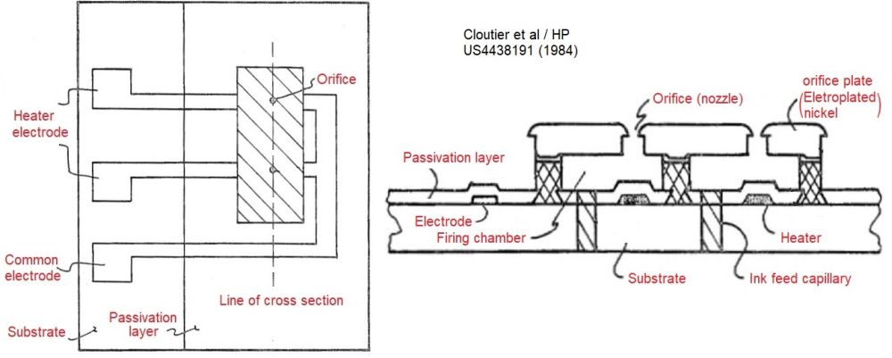
The principle of TIJ is that the pressure increase near the nozzle is not induced mechanically, but thermally. Although lasers were mentioned in one patent as a possible source, the most realistic approach was to use an electrical resistor. Physics teaches us that for a resistor, the power lost as heat is proportional to the current squared times the resistance. Thus a high enough resistance and the right amount of current can create local heating very quickly. Referring to the left-hand image below we can see how simple the principle is, and how analogous to the first PIJ design the first Canon invention was.
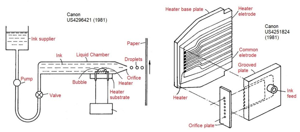
If you remember the early 1980s then you’ll recall that personal computers were fast becoming more accessible for the office and home, driving the need to produce “hard copy” printouts. This drove the need for cost effective solutions. What was different about thermal print head technology was that it was designed to have a scalable microfabrication process from the start. The mass-manufacturing processes already being used in electronic devices, like PCBs and silicon chips, could be quickly adapted to making TIJ heads. This, in turn, results in lower unit costs when making them in large numbers. The right-hand image above gives a first example of using thin film circuit technology to make a linear array of nozzles. Note that heater pads measure just 150 microns, meaning the nozzles are spaced sub-millimeter.
It is also useful to highlight at this point that unlike the PIJ inventions, which first used diluted versions of existing inks /fluids, the ink for thermal heads was developed alongside the mechanical parts so it would work as a system. This is because the action of the heater relies on the specific blends of solvents and the solid content of the ink to be chosen carefully. As looking into a kettle will demonstrate, heating elements can easily become contaminated! We’ll look at this topic again when we consider TIJ in more detail.
At around the same time as Canon, Hewlett Packard developed a competing thermal printhead. The manufacturing of high density ejectors was also a strong theme of the invention disclosure, although the image below demonstrates only two nozzles. The major step claimed was the fact that the head was manufactured using standard techniques in one piece, so-called monolithic, therefore avoiding complicated alignment procedures that are a possible source of manufacturing errors.
In the following 30 years, HP, Canon, and most recently, Memjet, have continued to develop the head manufacturing processes, based on what is now called Silicon-MEMs. Using this approach, HP especially has looked to dominate industrial print, using modular designs with an emphasis on scaling into PageWide print systems. We will come back to discussing in more detail what has made this successful.
VALVEJET HEADS GO WELL BEYOND INK
When the printed volume needs to be larger and the dot resolution of the printed pattern does not demand such a high precision, then valvejet-style devices can be very useful. The technology is also sometimes known as mechanical inkjet (MIJ).
Until the recent re-emergence of the technology in ceramic tile manufacturing, large character coding or high-coverage textile printing, like carpeting, were the main usage. Print heads of this category generally use pressurized ink supply that is forced through a relatively large nozzle, itself opened and closed by a mechanical actuator. Thus the devices act like an array of fluidic valves with the output being either very large drops, or a well-directed spray, depending on the design.
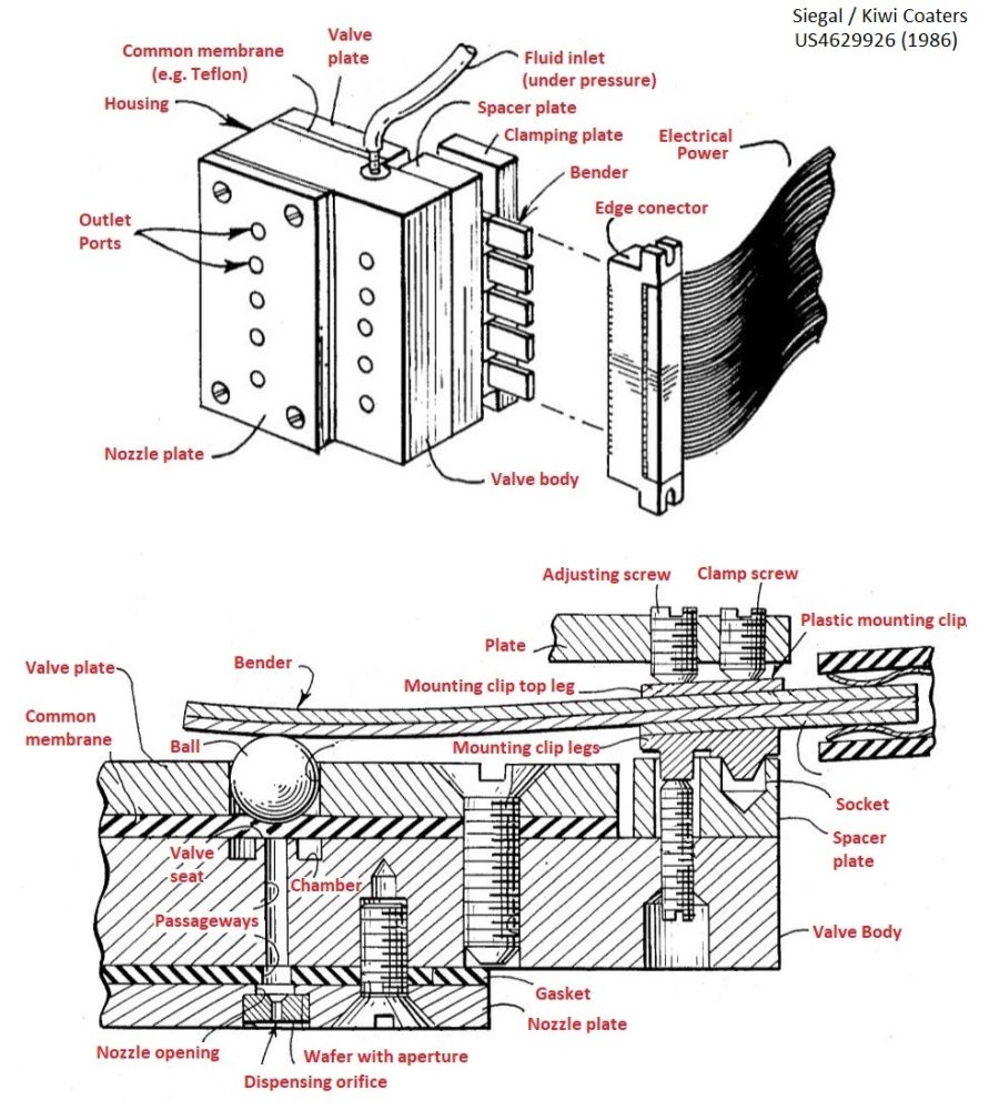
The image below shows an early design of valvejet, patented by US company Kiki Coders at the height of inkjet growth in the mid 1980s. The design relies on a PZT actuator that bends to seal a ball bearing against a planar valve seat using a PTFE membrane to achieve a reliable seal. To allow for mechanical differences each channel can be tuned with the adjusting screws.
Due to the large size of the parts, the printing frequency is normally much less than the CIJ or other DOD devices we’ve already discussed, although the dots are not needed so often. ReaJet advertise their DOD 2.0 systems are be able to work at an impressive 600 metres/minute.
The key advantage of valvejets is their ability to deposit larger volumes of material and “throw” drops large distances due to the high pressure that can be applied. This means the applications are truly industrial. For example, ReaJet describe the micro-dosing of oils onto cosmetic applicators for making assembly easier.
The viscosity range is generally much wider than is possible with other inkjet, which is a big driver for their use with higher solid content inks like ceramic glazes. With such abrasive particles present, however, the reliability comes down to the ability to re-seat the valve following many actuations and this has resulted in continuous invention. We will discuss ceramics applications, including using valvejets, in a separate post.
SUMMING UP
So now we have got a feeling for how the early print head designers got started. In later posts we will re-visit some examples and describe their design, as well as how it fits with the intended applications. For PIJ, this will encompass the different geometries versus contemporary manufacturers (KM, Fuji, Xaar etc) and the waveforms used to make them work. For TIJ and other DOD types the newer entrants, like MEMjet and Tonejet will be covered as well. As we just said, we will also see valvejets again soon.
Referenced Products and Resources
-
Which Printhead Should I Use?
Learn More -
Printheads
Learn More -
JetXpert Drop Analysis
Learn More