波形を最適化する方法
Last Updated on 3月 29, 2024 by ImageXpert Team
インクジェットの波形についての紹介記事では、波形とは何か、そしてその波形をプリントヘッドに適用するプロセスはどのようにおこなわれるのかを説明しました。ここでは、多くのプリントヘッドに適用できる一般的な液滴観測装置によるアプローチを用いて、より良い吐出をするために波形を最適化する方法を考えます。この記事では、Dimatix Sambaプリントヘッドを使って、段階的に画像やデータの例を紹介します。 introductory article on inkjet waveforms, we described what a waveform is and how the process of applying it to the printhead works. Now we consider how to optimize that waveform to get better jetting, using a general dropwatcher approach that applies to many printheads. For those of you that have received a waveform from your printhead or ink supplier, you may be wondering whether waveform optimization is necessary and worth your time and effort. In some cases, a generic waveform that is not tuned for a particular ink or industry application is good enough, but in many cases it is not.
To help explain, rather than printing images, let’s consider the process of taking images. On your digital camera there are settings for white balance, exposure, shutter speed, etc to help control how the image is captured. The camera comes with a preset combination of settings that will work well for general use, and this is probably what most people use – just point and click. But when you want to shoot images at night, or on a sunny day, or of a person, or of a landscape, a professional photographer is able to manipulate the settings to get much better results for each of these very different scenarios. Inkjet waveforms are very similar – there is such a difference in requirements between printing a coating, a graphic, a circuit board, or a metal part that a generic combination of waveform settings won’t be able to perform well in all of them. Nobody knows your ink and application like you do, so we want to bring you up to professional status with the knowledge to tune a generic waveform to get optimal results for your exact application.
In this article, we will follow along step-by-step with a Dimatix Samba G3L printhead to give example images and data along the way.
原理原則の再確認
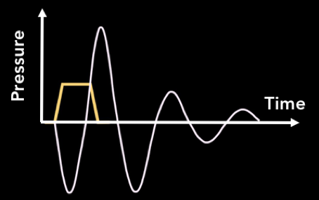
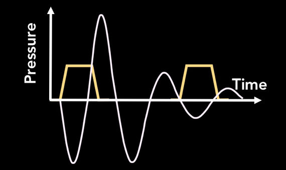
まず、プリントヘッドや波形に関する他の記事で説明した内容を簡単におさらいしましょう。左の図では、電圧パルスによってアクチュエータが変形し、加圧内に圧力が発生して液滴が吐出される様子を示しています。私たちは目標とする要件に合致した吐出がおこなわれるように、パルスのサイズ、形状、間隔を最適化します。
目標を理解する
The first step of any attempt to develop a waveform is to clearly define the goal. Usually, the most important targets to identify are the desired drop size, drop velocity, and jetting frequency. If you already know the target specifications, then you can get started straight away. If not, then you will have to do some investigation. Remember that different applications will have very different requirements for the jetting performance. Coating applications are primarily concerned with maximum throughput, and the stability at different speeds or number of satellites are of little concern. Contrast this to printed electronics, where printing consistency is everything. The printheads are very close to the surface, so slow drop velocities are acceptable, but no satellites and consistency in drop size across the printhead are crucial. Direct to shape applications have varying distances to the surface, so the drop speed and therefore throw distance should be maximized. 3D printing applications don’t want speeds that are too high (cause powder splash) or too low (won’t penetrate the powder). As you can see, you have to understand the needs of the application before beginning the process of tailoring a waveform to it.
If you are an ink company and have a specific machine to develop for, check with your customer what the usage conditions of the ink are. If your customer is an equipment manufacturer, they should be able to tell you all you need to know. If selling direct to user, then perhaps this information is not so easily available and you’ll have to work a bit harder to figure out what’s sensible.
One question that we are commonly asked is how to determine the necessary jetting frequency for your application. This is directly related to the printing resolution (in the process direction) and the carriage speed. In a simple example, let’s say you have one printhead printing at 600dpi and are printing in one pass at 100 inches per second. 600 dots per inch multiplied by 100 inches per second equals 60,000 dots per second – your jetting frequency! This equation gets a little more complicated when you print multiple passes or have multiple printheads. For example, if it took you two passes instead of one to print 600dpi, that means each pass is only 300dpi. Recalculating our frequency brings us to 30,000 dots per second. Instead of a single printhead, you had two printheads working together, that means each pass is really only 150dpi per head. Recalculating our frequency brings us to 15,000 dots per second for each head. With this basic knowledge, you can calculate how fast each printhead will be jetting on more and more complex machines to determine which frequency you should be optimizing your waveform for.
最適化の出発点
波形最適化の最初のステップは、液滴観測装置で観測できるように、インク吐出の適切なベースライン(基準線)を確立することです。可能であれば、プリントヘッドメーカーが推奨する、またはデフォルトのシングルパルス波形から始めるのが簡単な方法です。通常、パルスタイミングとともに、ある種の校正電圧(「ラベル」電圧と呼ばれることもある)がヘッドメーカーから提示されます。最初にこれを使用して、それなりに吐出できている状態を作ります。我々のDimatix Sambaの例では、プリントヘッドのユーザーマニュアルにある波形推奨値:パルス幅2.18us(40V/usの立ち上がり時間を含む)、振幅26Vのパルス、これをベースラインとして最適化を始めます。
次のステップは、液滴観測装置の視界に液滴を捉えることです。できればノズルプレートが見えることが重要で、これは吐出不良が起きたときに現象を理解するのに非常に役立ちます。以下の画像は、Dimatix Sambaプリントヘッドの理想的な観察状況です。
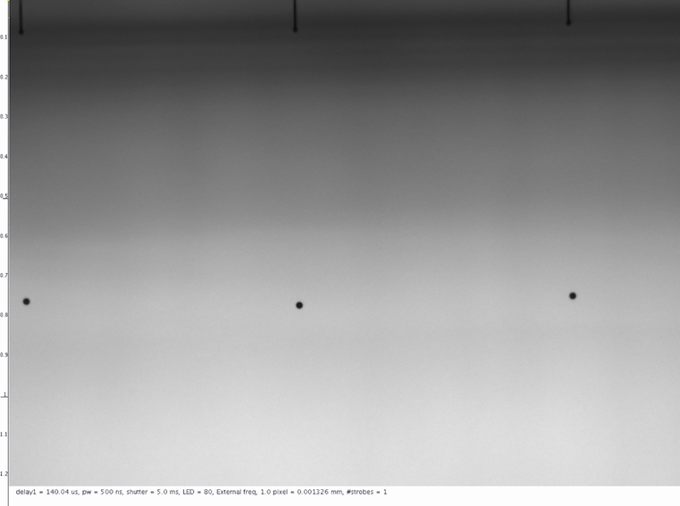
シリンジ充填で予備テストをするだけなら、テスト中のインク消費量を最小限に抑えることが可能です。8kHzほどの周波数で、同列の10~20個程度のノズルを吐出させれば、しばらくの間、インクを補充することなくテストをおこなうことができます。
上記条件で一度液滴速度を測定します。正常であれば5~6m/s程度の速度が出ているはずです。最終的な目標がそれ以上の液滴速度であっても、この設定であれば、サテライト滴はそれほど多く出ないため、容易に測定できます。速度が低すぎると感じた場合は、パルスの電圧を上げ下げしてみましょう。今回の例では、たまたま波形に手を加えなくても許容範囲内の速度が出ていたため、26Vは適切な設定だと思います。
ステップ1:パルス幅の最適化
波形最適化の最初のステップは、ヘッドとインクの組み合わせの音響特性に合った基本的なパルス形状を得ることです。波形の用語では、「適切なパルス幅を決定する」といいます。
ノズルサイズと液体の性質は変更できないので、インクがリズミカルに前後に波を起こすことができるように、加圧室を拡張する時間を設定するのです。
一般に、パルス幅と液滴体積および液滴速度との間には、二次関数に近い関係があります。最適パルス幅は最大の液滴体積と液滴速度を生成するパルス幅であるので、そのピークを見つけることが第1 の目的です。まずは現在のパルス幅を確認し、その推奨設定の 50%減から 50%増までのパルス幅で調整していきます。ヘッドから液滴までの距離を一定にしておき、各パルス幅で液滴体積と速度を測定することで、液滴体積カーブ・速度カーブを得ることができます。
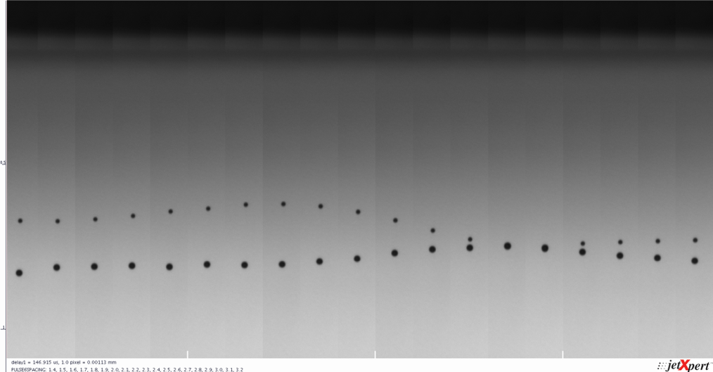
Samba プリントヘッドを使い、0.1us刻みでパルス幅を1.1〜3.3usの範囲で振ってみました(ダブルパルスを使用)。下の画像はJetXpert のオプションであるXSweep と Stitch を組み合わせて自動掃引、撮影したものです。 Xスウィープ and スティッチ.
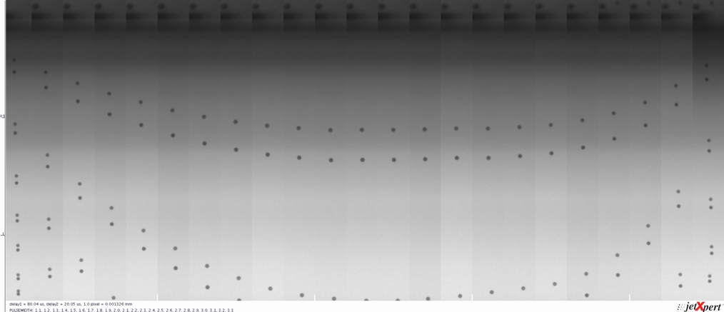
速度カーブの頂点部分が、お使いのインク・ヘッド・ヘッド駆動回路基板の組み合わせに対し、最も効率的な液滴吐出をおこなえるパルス幅です。サテライト滴の最適化も考慮し、ピークより少し高めのパルス幅を使用するのが好ましい場合もあります。パルス幅を選択したら、その値を波形にセットして、次に進みます
上の画像を見ると、2.1~2.2us のパルス幅が最も液滴速度が速いことがわかります。画像の各スライスは同じタイミングに撮影されたものですので、上記のパルス幅設定で液滴がプリントヘッドから最も遠くまで落下しています。2.18usが Dimatix 製 Samba ヘッドのマニュアルに記載されていた推奨パルス幅でした。実際にこの値が最適だと確認ができました。Dimatix、いい仕事してます!
時間の節約
インクジェットに限らず、この手の評価をどの程度の精度でおこなうかはユーザーの判断に委ねられます。波形の最適化の場合、各パラメータをテストするステップサイズを小さくすれば、より精度の高い結果が得られます。しかし、手動で解析を行う場合、ステップサイズを小さくすればするほど、テストにかかる時間が長くなります。ImageXpertにはXSweepというツールがあり、波形の設定変更と測定を自動的に繰り返してくれるので、このプロセスの高速化が図れます。 Xスウィープ, which will automatically adjust the waveform settings and perform the measurements for you.
Xスウィープ
Xスウィープを使えば、波形を最適化するプロセスの自動化をさらに進めることができます。電圧やパルス幅など、調整したい波形のパラメータを指定し、テストする値の範囲を入力するだけで、それぞれの画像とデータを自動的に取り込みます。
See Moreステップ2:電圧の最適化
タイミングがわかったところで、電圧と液滴体積、液滴速度の関係を把握しましょう。通常、電圧と液滴体積および液滴速度の間には、ある限界までは直線的な関係があります。通常のトレードオフは、電圧を上げるとリガメント(テール)が増えることです。ですから目的は、分裂してサテライト滴を形成するようなテールのない綺麗なドロップを形成できる範囲内で、可能な限り高い速度を得ることなのです。
先ほどのパルス幅と同様に、電圧値を振って、それぞれの電圧での液滴速度を測定してみましょう。ここで重要なのは、液滴体積とサテライト滴の形成状況も確認しておくことです。このステップでの目的は、サテライトの数が多すぎず、目標とする液滴体積と速度が得られる電圧値を決定することです。Sambaを使って、21V〜31Vの電圧を0.5V刻みで自動的に測定しました。結果は以下の写真のとおりです。
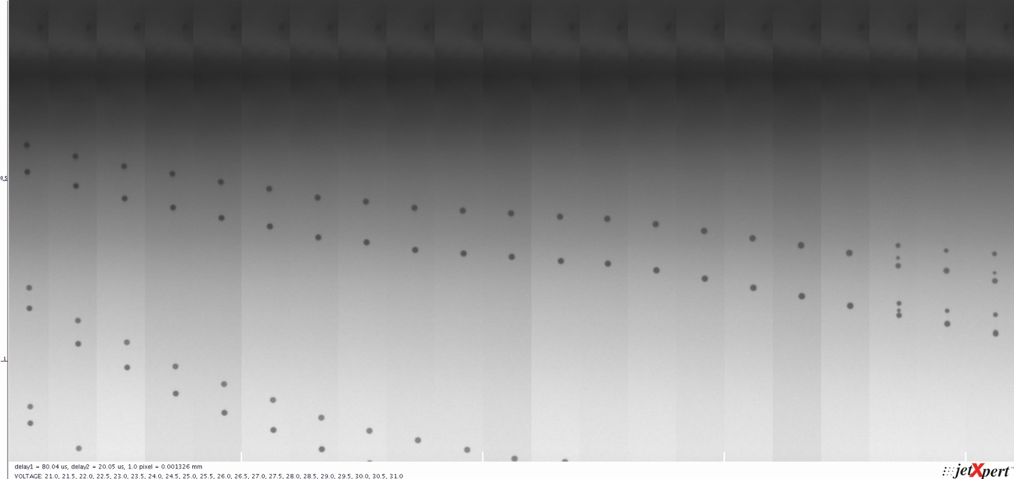
またしても、測定結果は理論と一致しているようです。サテライトが発生するところまで、液滴速度は電圧に対して直線的に増加しています。ここでは、サテライトが発生する電圧よりも少し低い電圧を選んで測定してみましょう。
これで、決定した設定値(パルス幅と電圧)の波形による液滴体積と液滴速度がわかり、目標値と比較できるようになりました。しかし、それで終了ではありません。
新しいことを学びたい方へ: 新着記事の配信を希望する
ステップ3:より強い圧力をかけてみる
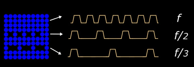
Now that you’ve improved your pulse and it’s producing the velocity you’ve been looking for, it is time to push the head a bit harder and turn up the frequency. This will test whether the waveform we’ve built so far performs well at our target frequency, as well as if there are any particular spots to avoid. If you already know what your key target frequency is, then you can save some time by just looking at jetting there, but don’t forget to include the subharmonics too. You may be surprised to learn that when an image is rendered and printed, the print resolution is not necessarily constant across the whole image. To help improve the appearance of the image, the resolution is increased for darker portions and decreased for lighter portions, making it possible to print a gradient even if you only have one available drop size. The resolution is commonly divided in half or in thirds, so testing one half and one third of your target frequency will ensure your waveform will still perform well after rendering.
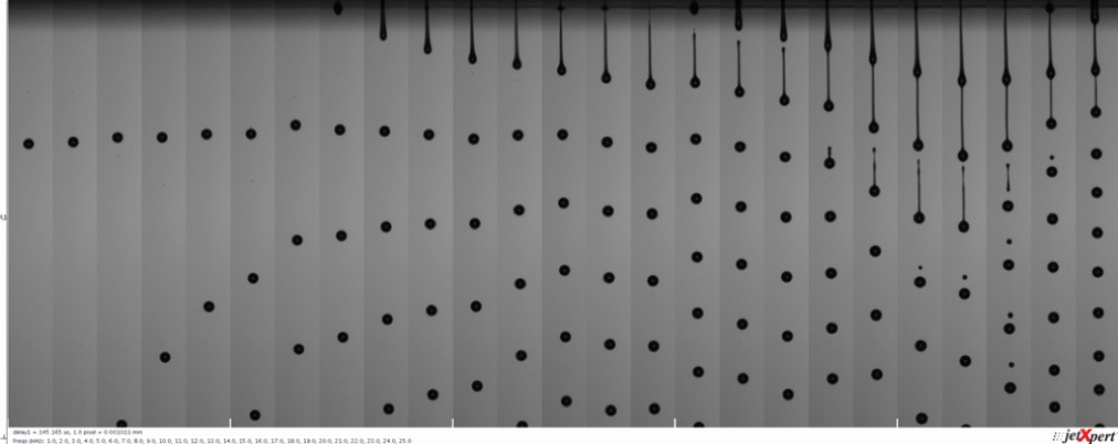
通常、あるインクにおいて全周波数での挙動を把握しておくことが最善だと考えられています。なぜなら、お客様が突然そのインクを別の周波数で使用したいと要望する可能性もあるからです。ImagexpertはXSweepに加えて、このプロセスを高速化するためのFrequency Sweepという周波数掃引アドオンを提供しています。下の画像は、Sambaに1~30kHzの範囲で1kHz刻みで波形を印加したときの吐出画像です。 Frequency Sweep Add-On to help speed up the process. This will automatically sweep through a range of frequencies and collect the data, which is especially helpful for higher frequency printheads. The image below is our Samba waveform jetting at 1 – 30kHz in 1 kHz steps.
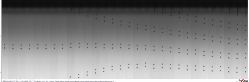
幸いなことに、この範囲ではドロップの形成はかなり良好です。ここで、別の例を見てみましょう。
19kHz付近までは一定の速度で吐出していますが、その後、速度が急上昇していることに注目してください。速度の増加に加えて、リガメントの長さの増加とサテライトの形成が見られます。前回の波形に関する記事に記載しているとおり、これは共振が起きていることによる結果です。19〜24kHzの範囲では、直前のパルスの勢いがノズルに残っていることで、波が増幅されるようなパルス間隔になっています。この知識があれば、その周波数を使用しないか、その範囲では別の波形を形成するなどの対応が可能です。
思うような測定結果が出ない場合
作成した波形が目標とする周波数でうまく動作しない場合は、より低い電圧でもう一度試しましょう。反復作業とはなりますが、パルス幅と電圧を少しずつ変更し、観察していきます。自動化がここで威力を発揮します。どうしても液滴体積や液滴速度を十分高くできない場合は、マルチパルスが役立ちます。
ステップ4:マルチパルスの使用
液滴を作成するための波形に 2 つ以上のパルスを使用する場合、それをマルチパルスと呼びます。これをグレースケールと混同しないでください。このテストでも 1 つの液滴しか生成しませんが、複数のパルス波形を使用します。マルチパルスは、単一のパルスが十分なインクを吐出できない場合に便利で、吐出される液滴体積を増加させることができます。
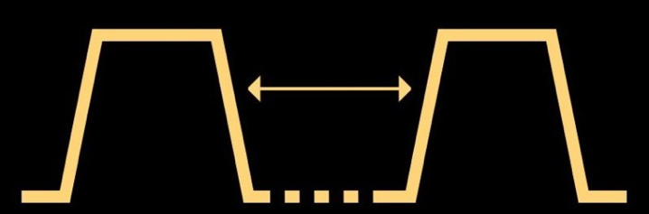
複数のパルスを使ってより大きな液滴を形成する場合、まず、ヘッド内でインクが移動するタイミングを理解する必要があります。そこで、同じパルスを2つ作り、その間隔を変えた場合の吐出への影響を見ていきます。タイミングがよければ、2回目のパルスによってノズル内のインクの運動量が増加し、より速い液滴が吐出されることになります。
先ほど作成したパルスを複製し、この2つのパルスの間隔を調整して、各パルス間隔での吐出を分析してみましょう。まず、間隔を許容範囲の最小値から各パルスのパルス幅の2倍まで変化させてみましょう。最も有効な測定方法は、2番目に出てくる液滴の速度を調べることです。なぜなら、2番目の液滴の速度が、最初のパルスに起因する圧力変動に非常に敏感であるためです。ヘッドとインクの組み合わせによっては、パルス間隔が狭い場合は測定する前に液滴が混ざり合う可能性があります。一方、二滴目以降の吐出が、最初のリガメントとくっついて見える可能性もあります。ここで重要なことは、測定可能な液滴速度が最も速くなるパルス間隔を見つけることです。作用のピークは、ヘッドが共振するところです。あるヘッドとインクの組合せにおいて最も適した波形というものは、共振周期またはその付近で作用し、入力値に対して吐出が最適化されます。
下の画像は最適化された Samba ヘッド用のパルスを複製し、0.1us刻みでパルス間隔を 1.4us から 3.2um まで掃引した様子です。2番目の液滴のスピードが最も速い場所がどこかは、明白ですね。ここが 1 番目と 2 番目のパルスが共振を起こしているポイントです。
共振周期が分かったので、それを使って波形を作ることができます。1 つ忘れてはならないのは、このようなパルスを次から次へと積み重ねる場合には電圧は増幅するということ考慮しなければな らい、ということです。そうでないと、最終吐出速度はとても速くなってしまいます。前述したように、これは通常ノズルプレートの濡れやサテライト滴にとって好ましくありません。その点を考慮して目標とする液滴体積を得るためには、次のような方法から始めると良いでしょう。
マルチパルスでグレースケールを作る
先に述べたように、グレースケールの大きな違いは、印刷画像のピクセルごとにドロップサイズを変えることができる点です。つまり、各グレーレベルに使用する波形パルスを選択して、希望する液滴体積を得る必要があります。これを達成するための最初のステップは、波形をプリントコントローラーで選択できるようにセグメントに分割することです。そして、適切なセグメントをグレーレベルに関連付ける必要があります。
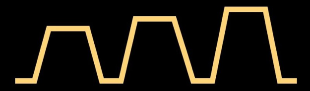
この部分は、パルス形状と同様に、システム、特に波形の「形状」を編集できるソフトウェアに大きく依存します。これをイメージする最も簡単な方法は、1パルスごとに波形を描き、各レベルでの使用状態を示す表を作成することです。この表は、5パルスの例を示しています。なおこのような手法は、波形制御に関する特許においてしばしば使用されています。
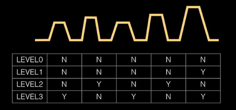
The reason we chose 5-pulse for 3 levels because it demonstrates nicely the high degree of flexibility that is possible, including the fact that pulse do not have to be identical or be linear in amplitude (like our first examples). The one thing to keep in mind is that the maximum frequency that can be used will be the inverse of the time taken to complete the whole waveform, regardless of which grey level you are selecting. For example, let’s say that you have three pulses in a waveform, each with a duration of 10us. Even if Gray Level 1 only uses a single 10us pulse, the maximum frequency that you can print at Gray Level 1 is based on 30us timing.
通常、電子回路基板が波形セグメントを切り替えるための時間を確保するために、各パルスの間隔をどこまで狭くできるかの限界値が存在します。ほとんどの優れた波形編集ソフトは、実現不可能な波形設定をした場合にそれを検知して通知してくれるようになっています。
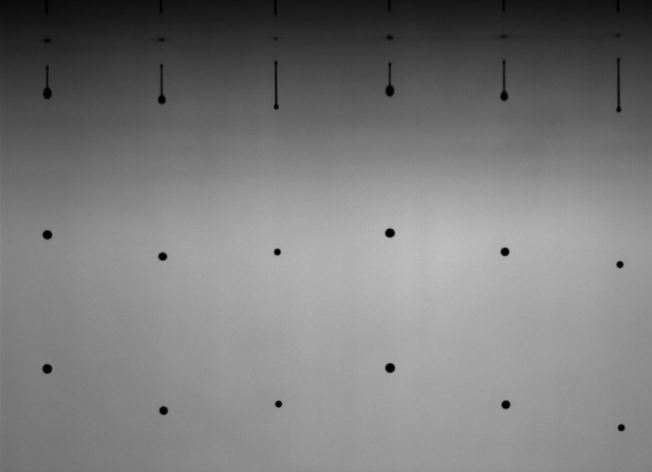
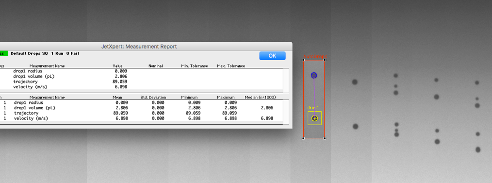
あとは、波形セグメントの個々のパルス幅、電圧、パルス間隔を調整して、液滴の体積と速度を目標に合わせて調整します。異なる大きさの液滴を同一画面上に捉えられると、すべてのグレーレベルへの変化の影響を調べることができるので便利です。この画像では、1つの視野内に3つの異なるグレーレベルの液滴を表示しています。
より高度な波形設計
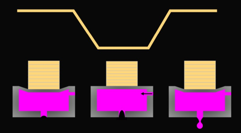
The multi-pulsing approach can also be useful for controlling nozzle plate wetting, or influencing ligament break-off, for example. Extra pulses can come before or after the main ejection pulse as shown below. Tips for implementing more advanced waveform tricks are hard to systematize but we wanted to make sure you know these things are possible. Two common types of pulses are pre-pulses and dampening / cancel pulses.
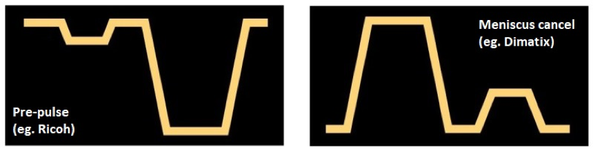
Pre-pulses are low amplitude pulses that come shortly before the main pulse, designed to help improve the efficiency of the ejection of the drop. They can help get the ink moving so that the ejection pulse has less energy to overcome (like rocking something before tipping it over). The timing of these pulses is critical to ensure that they are working with your main pulse and not against it!
Dampening pulses are a similar concept but appear at the end of the waveform. After a pulse, there is some residual energy within the ink and it will continue moving inside the nozzle until it fades away. This can cause trouble at high frequencies, because the next cycle is starting while there is still movement in the nozzle, potentially leading to harmonic behavior. A perfectly-timed dampening pulse will work against the residual motion of the ink in the nozzle, bringing it to a stop. Reducing the oscillations of the ink in the nozzle may also have other benefits such as reducing wetting or shorter ligament length.
Slew rate is another term that you may have encountered in your waveform studies. The piezoelectric material that the nozzle walls are made from can only react so quickly, so there is a limit to the amount of voltage that you can apply to them in short intervals. The slew rate is the change in voltage over the change in time, almost like the acceleration of the walls. Printheads call for the sloping edges of the waveforms to fall within a certain range of slew rates for safe operation. Manipulating the slew rate may have some impact on the waveform and can be explored, but it is not nearly as noticeable as pulse width or voltage.
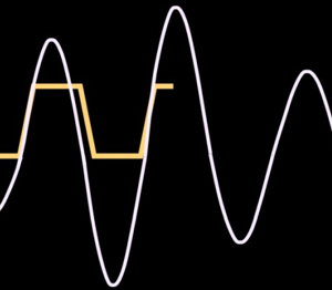
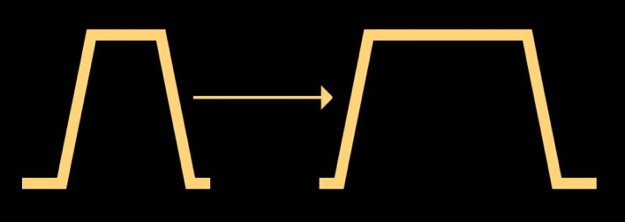
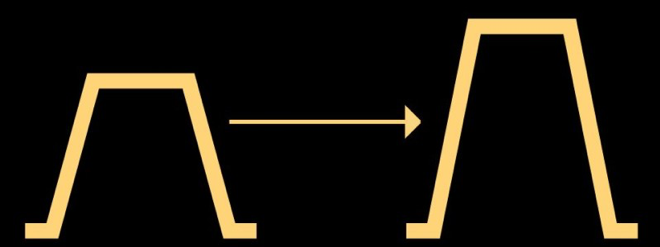
また、一部のヘッドメーカーが標準で採用している「バイポーラパルス」という方法もあります。これは、双方向 PZT を駆動するために、正極性および負極性アンプの両方を使用するヘッドから来ています。このようなシステムの利点は、低い電圧でより効率的にドロップを吐出できることですが、放出後の圧力変化を操作するために、任意の方向にパルスをプログラムすることもできます。バイポーラ機能はより複雑な電子回路が必要になるため、非ゼロのスタンバイ電圧を使用する単極性回路(正または負の電圧のみ)を用いて効果を再現することができます。下の図は、主要なヘッドメーカー2社の最近の特許から引用したもので、その違いを説明しています。左はバイポーラの波形、右は非ゼロのスタンバイ電圧を持つユニポーラの波形です。
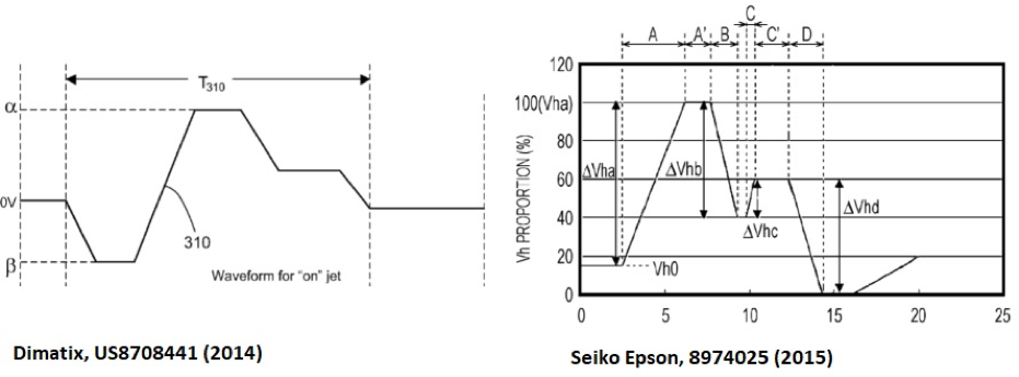
いずれの場合も、波形は前述したように一連の単純な台形よりも大きくなります。ユーザー指定の形状を生成するには、パルスの高さと幅だけでなく異なるアプローチが必要です。通常、波形は所定の時間に 1 つの電圧を他の電圧に変化させるまでのセグメントによって決定されます。これには特定の電子回路が必要で、ベンダー特有である場合もあります。これらのテクニックを用いる波形の最適化については、今後の記事で紹介できればと思います。