如何优化波形
Last Updated on 3 月 29, 2024 by ImageXpert Team
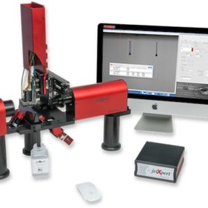
在我们关于喷墨波形的介绍性文章中,我们描述了什么是波形,以及如何将其应用于打印头的过程。现在我们考虑如何使用适用于许多打印头的通用 墨滴观测方法来优化该波形以获得更好的喷射效果。在本文中,我们将逐步地使用Dimatix Samba打印头来提供示例图像和数据。 introductory article on inkjet waveforms, we described what a waveform is and how the process of applying it to the printhead works. Now we consider how to optimize that waveform to get better jetting, using a general dropwatcher approach that applies to many printheads. For those of you that have received a waveform from your printhead or ink supplier, you may be wondering whether waveform optimization is necessary and worth your time and effort. In some cases, a generic waveform that is not tuned for a particular ink or industry application is good enough, but in many cases it is not.
To help explain, rather than printing images, let’s consider the process of taking images. On your digital camera there are settings for white balance, exposure, shutter speed, etc to help control how the image is captured. The camera comes with a preset combination of settings that will work well for general use, and this is probably what most people use – just point and click. But when you want to shoot images at night, or on a sunny day, or of a person, or of a landscape, a professional photographer is able to manipulate the settings to get much better results for each of these very different scenarios. Inkjet waveforms are very similar – there is such a difference in requirements between printing a coating, a graphic, a circuit board, or a metal part that a generic combination of waveform settings won’t be able to perform well in all of them. Nobody knows your ink and application like you do, so we want to bring you up to professional status with the knowledge to tune a generic waveform to get optimal results for your exact application.
In this article, we will follow along step-by-step with a Dimatix Samba G3L printhead to give example images and data along the way.
快速提醒原则
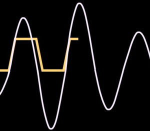
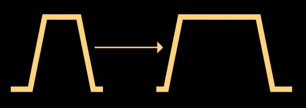
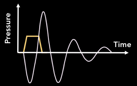
让我们首先简要回顾一下我们在其他打印头和波形文章中讨论的内容。在下面的示意图中,我们展示了电压脉冲如何导致压电陶瓷变形,在喷嘴室中产生压力并喷出墨滴。优化脉冲大小、形状和间隔,以确保喷射符合我们的目标要求。
了解你的目标
The first step of any attempt to develop a waveform is to clearly define the goal. Usually, the most important targets to identify are the desired drop size, drop velocity, and jetting frequency. If you already know the target specifications, then you can get started straight away. If not, then you will have to do some investigation. Remember that different applications will have very different requirements for the jetting performance. Coating applications are primarily concerned with maximum throughput, and the stability at different speeds or number of satellites are of little concern. Contrast this to printed electronics, where printing consistency is everything. The printheads are very close to the surface, so slow drop velocities are acceptable, but no satellites and consistency in drop size across the printhead are crucial. Direct to shape applications have varying distances to the surface, so the drop speed and therefore throw distance should be maximized. 3D printing applications don’t want speeds that are too high (cause powder splash) or too low (won’t penetrate the powder). As you can see, you have to understand the needs of the application before beginning the process of tailoring a waveform to it.
If you are an ink company and have a specific machine to develop for, check with your customer what the usage conditions of the ink are. If your customer is an equipment manufacturer, they should be able to tell you all you need to know. If selling direct to user, then perhaps this information is not so easily available and you’ll have to work a bit harder to figure out what’s sensible.
One question that we are commonly asked is how to determine the necessary jetting frequency for your application. This is directly related to the printing resolution (in the process direction) and the carriage speed. In a simple example, let’s say you have one printhead printing at 600dpi and are printing in one pass at 100 inches per second. 600 dots per inch multiplied by 100 inches per second equals 60,000 dots per second – your jetting frequency! This equation gets a little more complicated when you print multiple passes or have multiple printheads. For example, if it took you two passes instead of one to print 600dpi, that means each pass is only 300dpi. Recalculating our frequency brings us to 30,000 dots per second. Instead of a single printhead, you had two printheads working together, that means each pass is really only 150dpi per head. Recalculating our frequency brings us to 15,000 dots per second for each head. With this basic knowledge, you can calculate how fast each printhead will be jetting on more and more complex machines to determine which frequency you should be optimizing your waveform for.
起点
波形优化的第一步是为我们的喷射建立一个合理的基线,以便我们用dropwatcher进行查看。如果可能的话,一个简单的方法是从打印头制造商推荐的或默认的单脉冲波形开始。除了典型的脉冲定时,通常还会有某种校准电压(有时称为“标签”电压)。使用这个开始是因为它应该产生合理的喷射。对于我们的Dimatix Samba示例,我们将从打印头用户手册中的波形开始:脉冲宽度2.18us、振幅脉冲26V(包括40V/us上升时间)。
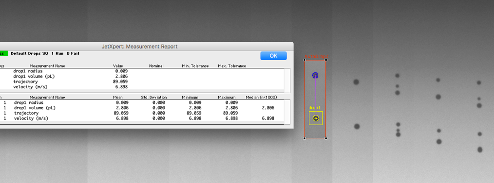
下一步是让墨滴在观墨仪器的视野中可见。如果可能的话,你能看到喷头面板是很重要的;如果你失败了,这些也对找到失败的原因有很大帮助。下图给出了Dimatix Samba打印头的理想视图。
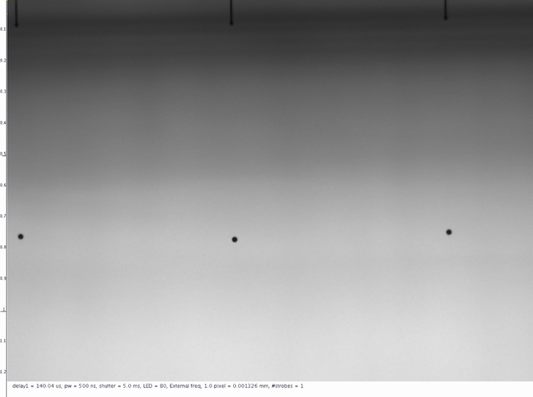
如果只用注射器填充进行初步测试,那么在测试中应最大限度地减少墨水消耗。以8kHz的中等频率选择喷头的同一行大约10-20个喷嘴进行喷射,可以在不需要补充液体的情况下测试一段时间。
快速测量下降速度以确保其合理,也许是5-6米/秒。即使最终目标更高,此设置通常也可以在没有太多卫星的情况下轻松测量。如果发现速度太慢,需要稍微增加脉冲电压,反之亦然。如果速度可以接受,则无需对波形进行修改,因此26V是一个合适的设置。
第一步:优化脉冲宽度
优化波形的第一步是获得基本的脉冲形状,以匹配头部和流体组合的声学特性。在波形术语中,我们将从确定合适的脉冲宽度开始。
因为喷嘴的尺寸和流体性质都是固定的,所以我们确定保持喷嘴室膨胀的时间,以使墨水在其中以良好的节奏来回移动。
一般来说,脉冲宽度与液滴体积和速度之间存在近似二次方关系。最佳脉冲宽度将产生最高的液滴体积和速度,因此找到峰值是我们的第一个目标。确定起始波形的当前脉冲宽度,并计划将脉冲宽度从低于建议设置的50%调整到高于建议设置的50%。在每个脉冲宽度下,测量距离打印头一致距离处的液滴体积和速度。选择一个合适的间隔,给出几个数据点,这样就可以建立一条曲线。
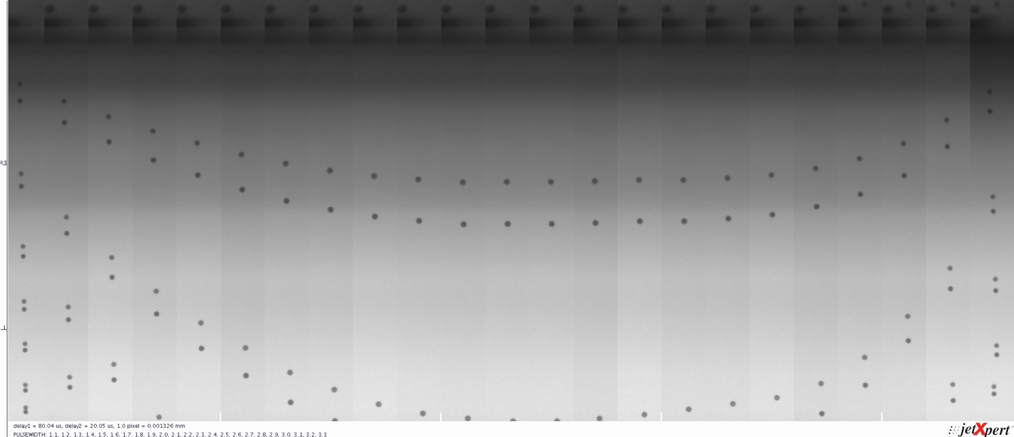
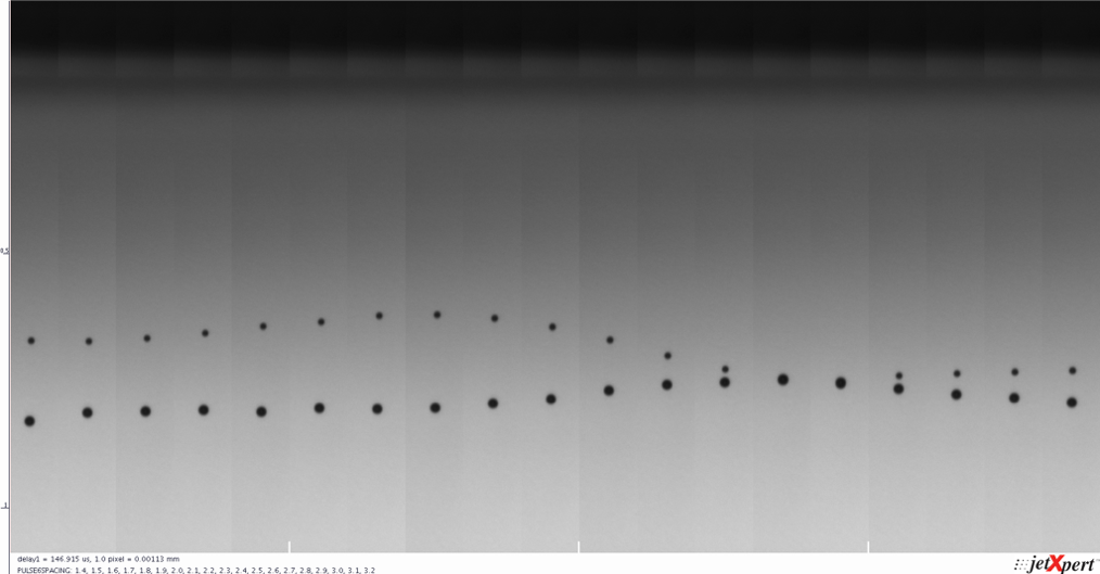
对于我们的Samba打印头,我们将自动以0.1微秒的增量扫描从1.1微秒到3.3微秒的脉冲宽度。通过在每个值(使用双脉冲)捕获图像,我们能够快速判断下落的速度,并在需要时补充测量值。下图是使用XSweep和Stitch的组合生成的。 XSweep and 缝线.
速度曲线的顶部是脉冲定时为墨水、喷头和电子设备的组合提供最有效的墨滴喷射的位置。有时需要使用比峰值稍高一点的脉冲宽度,因为它可以减少卫星。获得一些经验会帮助你做出这个决定。一旦你选择了你的脉冲宽度,将该值编程到你的波形中,然后继续下一步。
根据我们的图像,可以看到2.1-2.2微秒的脉冲宽度似乎产生了最高的液滴速度。我们可以分辨,因为图像的每一片都是在同一时刻拍摄的,并且墨滴在这些片中离打印头最远。如果你还记得,2.18us是我们在Dimatix Samba手册中的起始脉冲宽度,事实上它似乎是最佳的。干得好Dimatix !
节省时间
就像喷墨打印中的大多数设置一样,用户可以自行决定处理过程的精确度。在波形优化的情况下,选择较小的间隔来测试每个参数将能够给你更精确的结果。然而,当手动进行这种分析时,较小的间隔意味着进行这种测试所需的时间增加。为了加快进程,ImageXpert有一个名为XSweep的工具,它会自动调整波形设置并为您执行测量。 XSweep, which will automatically adjust the waveform settings and perform the measurements for you.
第二步:优化电压
现在我们确定了正确的时间,可以探索电压和下降体积和速度之间的联系。通常,电压与液滴体积和速度之间存在线性关系,直至达到限度。增加的电压也会产生增加的韧带,所以目标是获得尽可能高的速度,产生一个漂亮的干净的水滴,而没有拖尾打断卫星。
正如我们之前确定脉冲宽度 的方法一样,让我们尝试一系列电压,并测量每个电压下的液滴速度。关注墨滴体积和卫星形成也很重要,因为这会影响我们的决策。在这一点上,目标是确定电压设置,在没有太多卫星的情况下,为我们提供目标体积和速度。借助Samba,我们将自动以0.5V的增量扫描21V-31V的电压。输出如下所示。
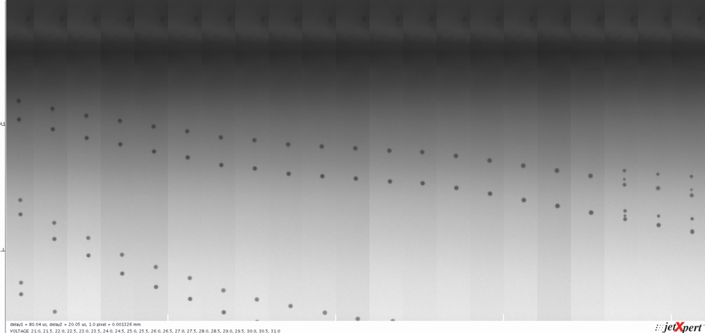
结果似乎再次与理论相符。液滴速度随电压线性增加,直至引入卫星点。因此选择一个比产生卫星的电压低一点的电压进行测量。
我们现在知道使用这些设置的波形将产生的液滴体积和速度,可以将其与我们的目标进行比较。但我们的工作还没有完成。
学习新东西?订阅以接收未来文章
第三步:增加打印频率
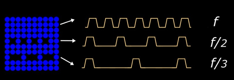
Now that you’ve improved your pulse and it’s producing the velocity you’ve been looking for, it is time to push the head a bit harder and turn up the frequency. This will test whether the waveform we’ve built so far performs well at our target frequency, as well as if there are any particular spots to avoid. If you already know what your key target frequency is, then you can save some time by just looking at jetting there, but don’t forget to include the subharmonics too. You may be surprised to learn that when an image is rendered and printed, the print resolution is not necessarily constant across the whole image. To help improve the appearance of the image, the resolution is increased for darker portions and decreased for lighter portions, making it possible to print a gradient even if you only have one available drop size. The resolution is commonly divided in half or in thirds, so testing one half and one third of your target frequency will ensure your waveform will still perform well after rendering.
我们认为通常最好尽可能了解整个频率空间。您已经设置好了系统,并且您永远不知道客户何时会要求以另一种频率使用该墨水。除了XSweep之外,Imagexpert还提供频率扫描附加组件,以帮助加快过程。这将自动扫描一系列频率并收集数据,这对于较高频率的打印头尤其有用。下图是我们以1千赫的步长以1–30千赫喷射的Samba波形。 Frequency Sweep Add-On to help speed up the process. This will automatically sweep through a range of frequencies and collect the data, which is especially helpful for higher frequency printheads. The image below is our Samba waveform jetting at 1 – 30kHz in 1 kHz steps.
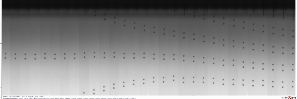
幸运的是,我们的打印效果在这个范围内看起来相当不错。这里是另一个例子,讲述了一个不同的故事。
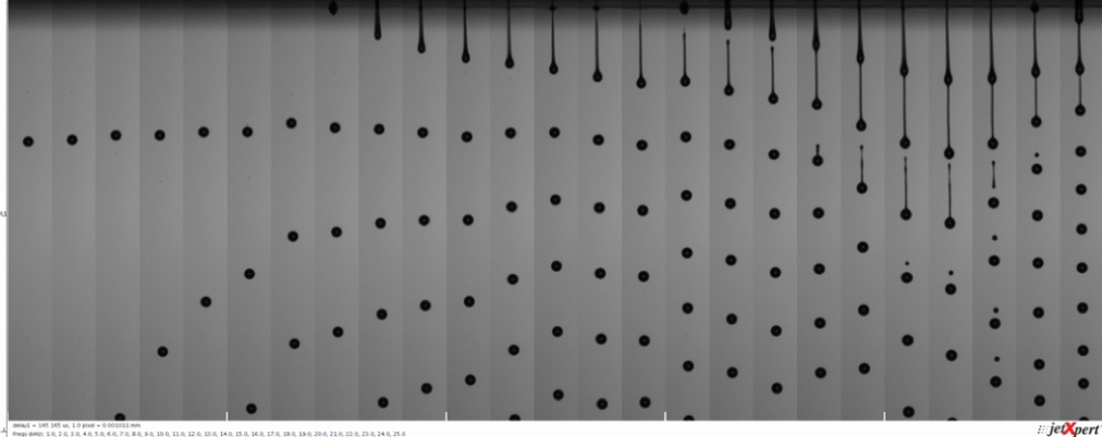
注意喷射是如何以恒定的速度进行的,直到大约19千赫,然后速度激增?除了速度增加,我们还看到韧带长度和卫星点形成增加。如果你回忆一下我们之前的波形文章,这就是共振在起作用。在19–24千赫时,在这个打印频率下,即脉冲被之前脉冲在喷嘴中的滞留动量放大。有了这些知识,您可以修改系统的设计,以避免该频率,或者为该范围使用不同的波形。
如果结果不好怎么办?
如果您创建的波形在目标频率下表现不佳,请选择较低的电压,然后重试。这是一个反复的过程,你可能需要对脉冲宽度和电压进行微小的改变,然后重复进行,以获得你想要的结果。这就是自动化派上用场的地方。如果你似乎不能让你的液滴体积或速度足够高,多脉冲可能会有所帮助。
第四步:引入多重脉冲
当波形中使用多个脉冲来产生液滴时,我们称之为多重脉冲。这个不要和灰度混淆;我们仍然只产生一种液滴尺寸,只是使用多个波形脉冲来实现。如果单个脉冲不能喷射足够的墨水,则多次脉冲对于增加喷射墨滴的体积是有用的。
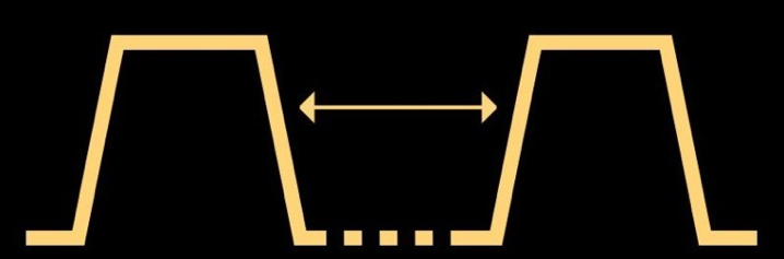
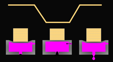
如果我们要使用多个脉冲来产生更大的墨滴,我们必须从了解墨水在打印头中移动的基本时间开始。我们通过产生两个相同的脉冲来实现这一点,并根据它们之间的间隙来观察喷射发生了什么,如下所示。当时机合适时,喷嘴中的墨水动量会因第二个脉冲而增加,一旦喷射出来,我们会看到更快的下降。
让我们复制之前创建的优化脉冲,并调整这两个脉冲之间的间距,分析每一步的喷射。 一个好的起点是改变间隔,从最小允许值到每个脉冲宽度的两倍。 最好的测量方法是观察第二个流出的液滴的速度(如果有的话),因为这个液滴的速度对第一个脉冲引起的压力波动非常敏感。 在一些头/墨水组合的低脉冲间隙中,液滴很可能在你有机会测量它们之前就已经合并了,而在其他情况下,第二次喷射可能会出现在第一次韧带上的凸起。 重要的是找出在什么间隔下你可以测量到的下降速度最快。大多数成功的灰度波形都是在共振周期或共振周期附近工作的,因此在给定输入量的情况下,喷射是最优化的。
当我们复制我们优化的Samba脉冲,并以0.1微秒的步长将脉冲间隔从1.4微秒扫描到3.2微秒时,我们产生了以下图像。很明显,第二次下降的速度是最高的,这是我们的共振期。
既然我们知道了共振周期,就可以建立一个使用它的波形。唯一要记住的是,如果你要像这样一个接一个地叠加脉冲,重要的是要考虑电压幅度,否则你会把最终的喷射速度推得很高。正如我们之前讨论过的,这对喷嘴润湿和卫星点通常是一件坏事。因此,考虑到这一点,您可以从这些开始,以获得您的目标液滴大小。
制作多脉冲灰度
正如我们已经提到的,灰度的主要区别是能够改变打印图像上每个像素的墨滴大小。这意味着您需要为每个灰度级选择要使用的波形脉冲,以获得所需的液滴大小。实现这一点的第一步是将波形分成可由打印控制器选择的段。然后,您必须将正确的线段与灰度关联起来。
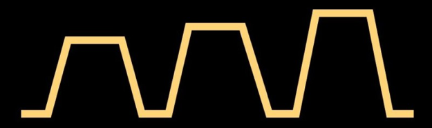
就像脉冲形状本身一样,这部分非常依赖于你的系统,尤其是允许你编辑波形“形状”的软件。最简单的可视化方法是用分隔符绘制波形,然后用表格告诉你每一级使用哪一个,这种方法经常在专利中使用。我们在下面画了一个5脉冲的例子。
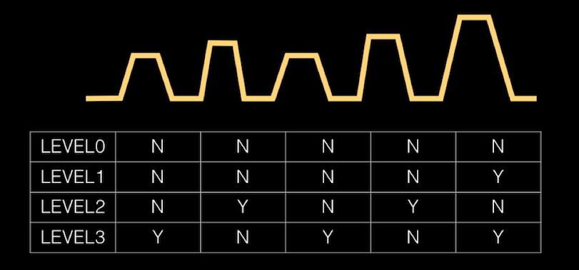
The reason we chose 5-pulse for 3 levels because it demonstrates nicely the high degree of flexibility that is possible, including the fact that pulse do not have to be identical or be linear in amplitude (like our first examples). The one thing to keep in mind is that the maximum frequency that can be used will be the inverse of the time taken to complete the whole waveform, regardless of which grey level you are selecting. For example, let’s say that you have three pulses in a waveform, each with a duration of 10us. Even if Gray Level 1 only uses a single 10us pulse, the maximum frequency that you can print at Gray Level 1 is based on 30us timing.
通常有一些规则与脉冲之间的距离有关,以便电子板有时间在波形段之间切换。大多数好的波形编辑器会告诉你是否会有问题。
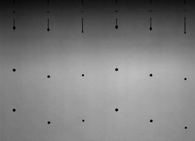
现在,您可以调整单个脉冲宽度、电压和波形段的脉冲间隔,以获得符合目标的液滴体积和速度。将不同大小的水滴并排放置在同一视场中是很有用的,这样您就可以研究变化对所有灰度级的影响。该图像在一个视场中显示了三个不同的灰度级。
高级波形设计
The multi-pulsing approach can also be useful for controlling nozzle plate wetting, or influencing ligament break-off, for example. Extra pulses can come before or after the main ejection pulse as shown below. Tips for implementing more advanced waveform tricks are hard to systematize but we wanted to make sure you know these things are possible. Two common types of pulses are pre-pulses and dampening / cancel pulses.
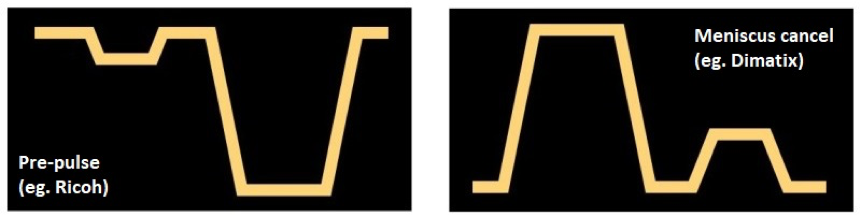
Pre-pulses are low amplitude pulses that come shortly before the main pulse, designed to help improve the efficiency of the ejection of the drop. They can help get the ink moving so that the ejection pulse has less energy to overcome (like rocking something before tipping it over). The timing of these pulses is critical to ensure that they are working with your main pulse and not against it!
Dampening pulses are a similar concept but appear at the end of the waveform. After a pulse, there is some residual energy within the ink and it will continue moving inside the nozzle until it fades away. This can cause trouble at high frequencies, because the next cycle is starting while there is still movement in the nozzle, potentially leading to harmonic behavior. A perfectly-timed dampening pulse will work against the residual motion of the ink in the nozzle, bringing it to a stop. Reducing the oscillations of the ink in the nozzle may also have other benefits such as reducing wetting or shorter ligament length.
Slew rate is another term that you may have encountered in your waveform studies. The piezoelectric material that the nozzle walls are made from can only react so quickly, so there is a limit to the amount of voltage that you can apply to them in short intervals. The slew rate is the change in voltage over the change in time, almost like the acceleration of the walls. Printheads call for the sloping edges of the waveforms to fall within a certain range of slew rates for safe operation. Manipulating the slew rate may have some impact on the waveform and can be explored, but it is not nearly as noticeable as pulse width or voltage.
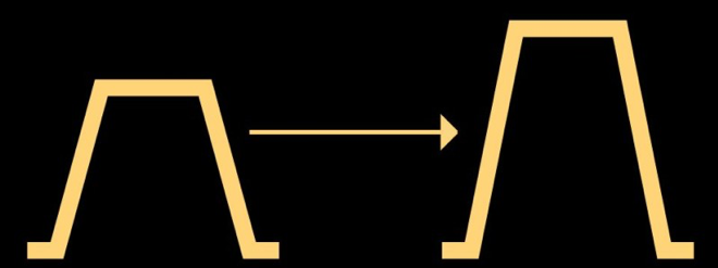
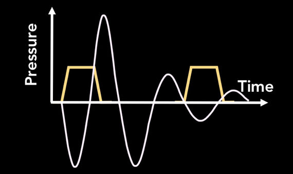
还有一种方法被一些领先制造商用作标准,称为双极脉冲。该术语来自使用正负放大器在两个方向驱动压电陶瓷的喷头。这种系统的优点是可以从较低的总电压获得更有效的液滴喷射,但它也允许在任何方向上对脉冲进行编程,以控制喷射后的压力变化。由于双极能力使电子设备更加复杂,因此可以使用单极电路(仅正极或负极电压)来重建这种效果,该电路使用非零的剩余电压。我们试图用下面的图片来解释这种差异,这张图片取自两家主要喷头制造商最近的几项专利。左边的图像是双极波形,右边的图像是具有非零剩余电压的单极波形。
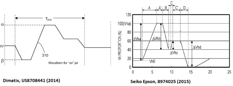
在这两种情况下,波形不仅仅是我们之前描述的一系列简单的梯形。生成更任意的形状需要一种不同的方法,而不仅仅是脉冲的高度和宽度。通常,波形现在由在给定时间内从一个电压变化到另一个电压的段来定义。需要一些特定的电子设备,这可能是供应商特定的。使用这些技术优化波形可能会在以后的文章中详细阐述。